Windage Loss Reduction

High Speed Electrical Machinery Windage

In 2012, Xdot Engineering and Analysis completed a Phase I/Phase II SBIR effort funded by the US Air Force. This goal of the project was to develop methods of reducing windage loss in high speed electrical machinery in the range of 50 kW to 200 kW. The project consisted of an extensive Computational Fluid Dynamic (CFD) analysis and optimization effort combined with rig testing in a new test rig to generate an experimental validation dataset and demonstrate a windage loss reduction technique.

Overall, the effort was successful. Major accomplishments include:

  • Production and commissioning of a new windage loss test rig capable of accurate, high resolution rotor windage torque measurements in relevant test articles at speeds up to 60,000 rpm.
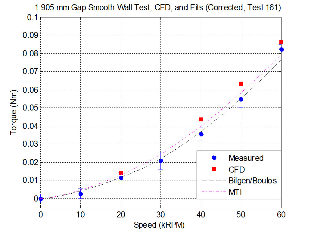
  • Measurement of windage torque for test articles with air gaps of 0.635, 1.270, and 1.905 mm over the speed range of 10,000 to 60,000 rpm, including:
    • Smooth wall stator test articles versus a smooth surface rotor.
    • Recessed wall stator test articles versus a smooth surface rotor (recesses intended to represent winding slots).
  • Development of an automated CFD analysis module to analyze windage torque for relevant geometries.
  • Prediction of windage torque for baseline cases and validation of the predictions against experimental data.
  • Exploration and optimization of several approaches to decreasing the windage torque by as much as 20 percent relative to a baseline condition.
  • Demonstration of one of these approaches in hardware.
  • Exploration of the effects of several key design windage related design features.

The major outcomes of this effort are:

  • Production of a relatively easy to use ANSYS/CFX analysis module for predicting windage torque in small gaps representative of the rotor-stator gap in this class of machinery.
  • Production of a unique, 60,000 rpm capable, high resolution windage loss measurement test rig.
  • Production of a new database of experimental measurements of windage torque for relevant test articles.
  • Prediction of several ways to reduce or minimize windage power loss and parameters that can be varied to affect windage loss during design.

Phase II Test Rig

Test Rig Side View

Reduced Test Data, CFD and Equations for 1.905mm Gap Smooth Wall


Evolution And Trend Of API 617 Compressor Rotordynamic Criteria

Evolution And Trend Of API 617 Compressor Rotordynamic Criteria

Pettinato, B.C., Kocur, J.A., Swanson, E.E., 2011
Turbomachinery, Transactions of the Turbomachinery Society of Japan

This paper traces the history of the American Petroleum Institute acceptance standards for compressor machinery dynamics. This examination starts with the 1st edition of the API 617 standard published in 1958 and concluding with the 7th edition of API 617 along with potential modifications proposed for the 8th edition.

Rotordynamic Design Audits Of AMB Supported Machinery

Rotordynamic Design Audits Of AMB Supported Machinery

Swanson, E.E., Maslen, E.H., Li, G., Cloud, C.H., 2008
Proceedings of the Thirty-Seventh Turbomachinery Symposium, Turbomachinery Laboratory, Texas A&M University, College Station, Texas

Active Magnetic Bearings (AMBs) are a mature bearing technology that is being applied to many new turbomachines. They have become the bearing of choice for most new turbo-expander applications. They are seen as a key enabling technology for compact, high speed, high power density direct drive generators and turbomachinery. As more and more units are fielded, it will become important that end-users and analysts have the tools and background to evaluate the rotor dynamics of AMB supported machinery.\n\nThis tutorial provides a basic review of AMB subsystems and key issues that need to be considered for a rotordynamic audit. Applicable API and ISO standards are reviewed from the perspective of evaluating the rotordynamic performance of AMB machinery. The tutorial concludes with an example audit of an existing AMB supported machine.

Rotordynamic Considerations For Foil-Bearing-Supported Rotors Operating Above A Bending Critical Speed.

Rotordynamic Considerations For Foil-Bearing-Supported Rotors Operating Above A Bending Critical Speed

Chen, H.M., Swanson, E.E., Walter, T.J., 2006
International Joint Tribology Conference, Paper IJTC2006-12118.

In meeting goals for higher energy density and efficiency for micro-turbomachinery, there is a trend towards higher operating speeds. Gas-lubricated foil bearings historically have provided a key enabling technology for this class of machinery due to their low power loss, high-speed capability in very low to very high temperatures, and process compatibility. Foil bearings have demonstrated very good performance in many rigid rotor applications. To meet future needs, however, micro-turbomachinery will be required to operate above a bending critical speed where shaft flexibility plays a dominant role. Some successes with foil bearing rotors operating in this region have been achieved, indicating that foil bearings can be built with the required dynamic characteristics. However, these efforts have been primarily experimentally driven, and published results indicate attention to such issues as bearing internal friction, rotor balance, rate of rotor speed change, and bearing location are crucial to success. This work presents an analytical examination of these issues. Using a modal solution for the bending critical mode of a simple, symmetric rotor, various relationships between foil bearing parameters and machine design elements are explored.

Bump Foil Damping Using A Simplified Model

Bump Foil Damping Using A Simplified Model

Swanson, E.E., 2006
ASME Journal of Tribology

Abstract

Foil bearings are a key enabling technology for advanced and oil-free rotating machinery. In certain applications, they provide a level of performance that is difficult or impossible to match with other technologies. A number of reasonably successful analytical techniques to predict bearing load capacity, power loss, and stiffness have been developed. Prediction of damping, however, has remained problematic. This work presents a fresh look at the damping problem. Using a simplified representation of a bump foil, this work considers explicitly adding the load dependence of the friction force. This approach is shown to provide a good match to previous experimental data. Parametric study results for the various model parameters are presented to examine the characteristics of this model. It is concluded that the load-dependent frictional force is important to consider for a bump foil damping model.

A Practical Review Of Rotating Machinery Critical Speeds And Modes

A Practical Review Of Rotating Machinery Critical Speeds And Modes

Swanson, E.E., Powell, C.D., Weissman, S., 2005
Sound and Vibration, May, pp. 10-17.

The goal of this article is to present a practical understanding of terminology and behavior based in visualizing how a shaft vibrates, and examining issues that affect vibration. It is hoped that this presentation will help the nonspecialist better understand what is going on in the machinery, and that the specialist may gain a different view and/or some new examples.

Fixed-Geometry, Hydrodynamic Bearing With Enhanced Stability Characteristics

Fixed-Geometry, Hydrodynamic Bearing With Enhanced Stability Characteristics

Swanson, E.E., 2005
Tribology Transactions, 48, pp. 82-92.

Abstract

This article presents the results of a successful bearing optimization study aimed at identifying a fixed-geometry, hydrodynamic journal bearing that does not suffer from the low load instability typical of this class of bearings. This goal was met through optimization of a fairly simple objective function based on the rigid rotor whirl-speed ratio, using a constrained, nonlinear algorithm based on sequential quadratic programming. In the interests of reducing computational time, a two-dimensional isoviscous formulation of the Reynolds equation was used for this work. The equation was solved using a finite element approach.This article includes a discussion of the optimization approach, the finite element solution approach, the resulting bearing design, and its performance characteristics. It concludes with an application example comparing the optimized bearing’s predicted performance to a tilting-pad bearing’s predicted performance for a centrifugal compressor-like rotor. The mismatch between shaft and bearing stiffness due to the rigid rotor optimization makes the optimized bearing less desirable from an unbalance response point of view. However, the optimized bearing is shown to have very good stability characteristics, which compare favorably to a tilting-pad bearing.

Testing Of A Centrifugal Blood Pump With A High Efficiency Hybrid Magnetic Bearing

Testing Of A Centrifugal Blood Pump With A High Efficiency Hybrid Magnetic Bearing

Locke, D., Swanson, E., Walton, J., Willis, J.P., Heshmat, H., 2003
ASAIO Journal, 49, pp. 737-743.

The purpose of this article is to present test results for a second generation, high efficiency, nonpulsatile centrifugal blood pump that is being developed for use as a left ventricular assist device (LVAD). The LVAD pump uses a hybrid passive-active magnetic bearing support system that exhibits extremely low power loss, low vibration, and high reliability under transient conditions and varying pump orientations. A unique feature of the second generation design configuration is the very simple and direct flow path for both main and washing blood flows. The pump was tested in both vertical and horizontal orientations using a standard flow loop to demonstrate the performance and durability of the second generation LVAD. Steady state and transient orientation pump operating characteristics including pressure, flow, speed, temperatures, vibration, and rotor orientation were measured. During the tests, pump performance was mapped at several operating conditions including points above and below the nominal design of 5 L/min at 100 mm Hg pressure rise. Flow rates from 2 to 7 L/min and pressure rises from 50 to 150 mm Hg were measured. Pump speeds were varied during these tests from 2,500 to 3,500 rpm. The nominal design flow of 5 L/min at 100 mm Hg pressure rise was successfully achieved at the design speed of 3,000 rpm. After LVAD performance testing, both 28 day continuous duty and 5 day transient orientation durability tests were completed without incident. A hydrodynamic backup bearing design feasibility study was also conducted. Results from this design study indicate that an integral hydrodynamic backup bearing may be readily incorporated into the second generation LVAD and other magnetically levitated pump rotors.

The Role Of High Performance Foil Bearings In An Advanced, Oil-Free, Integral Permanent Magnet Motor Driven, High-Speed Turbo-Compressor Operating Above The First Bending Critical Speed

Swanson, E.E., Heshmat, H., Shin, J.S., 2002
ASME paper GT-2002-30579.

The demand for high power density, reliable, low maintenance, oil-free turbomachinery imposes significant demands on the bearing system.  The full benefits of high speed, permanent magnet driven machines, for example are realized at speeds exceeding the capabilities of rolling element bearings.  The high speeds, and a desire for oil-free operation also make conventional liquid lubricated bearings an undesirable alternative.  The modern, oil-free foil bearing provides an excellent alternative,  providing low power loss, adequate damping for supercritical operation, tolerance of elevated temperatures and long life.  In this paper, the application of modern foil bearings to a high speed, oil-free turbo-compressor is discussed.  In this demanding application, foil bearings support a 24 pound, multi-component rotor operating at 70,000 RPM with a bending critical speed of approximately 43,000 RPM.  Stable and reliable operation over the full speed range has been demonstrated.  This application also required low bearing start-up torque for compatibility with the constant torque characteristic of the integral permanent magnet motor.  This work discusses the rotor bearing system design, the development program approach, and the results of testing to date.  Data for both a turbine driven configuration, as well as a high speed integral motor driven configuration are presented.